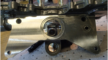
Inspection for Cracks on Airframe

Just to add to the excellent article by Mr. Frinchaboy, dated 17 April, I just wanted to give a short
explanation as to the “WHY” cracks are so relevant in this area. In photo above the red arrow shows the right hand cap at BL14R, at FS 129. This particular cap angle was reinforced as part of
the Huey II structural upgrade. As commonly known, the main beams at stations 14Left and 14Right are the foundation for the Huey structure.
These main beams run from the nose all the way aft to the oil coolercompartment (on single engine acft). All surrounding major structural components to include the pylon walls, the lift beam, engine" decks, engine mounts, and even the tail boom mounts are all tied directly to the left and right main beams.

The location outlined in photo A is known for possible cracks, especially for an airframe that has seen extensive cargo haul usage. This problem is one that has been known for years and in the second photo above I will attempt the explanation.
As we think back to our Aviation Physics 101 class, there a four forces that act on a flying aircraft at all time. They are Thrust, Drag, Lift, and Gravity. For this application we’ll only look at Lift and Gravity. In photo above the larger arrow, pointing up, shows the lift gernerated by the main rotor.
As we all know, the main rotor is connected to the transmission, which is connected to the Lift Link, in turn connected to the Lift Beam which is attached to the pylon walls. The pylon walls are the strongest piece of structure in the Huey. The forward pylon wall starts at FS 129.
Looking at the red right angle bars in photo B it will start to give you an idea to weakness of the FS129 area. As the aircraft flies thru the air, all the weight FORWARD of FS129 tends to gravitate down, to include the cabin and the cockpit, as shown by the smaller red arrow pointing down. I hope this gives a better idea of what needs to be looked at as Mr. Frinchaboy explained.


